Ball Balancing Robot
Mechanical Design / Mechatronics / PID Control
For my winter quarter independent study project, I set out to build my own version of a BallBot, a dynamically stable / statically unstable robot. I designed my bot from CAD to control algorithm, utilizing 3D printing, laser cutting, and C programming on an RP2040 microcontroller.
Mechanical Design
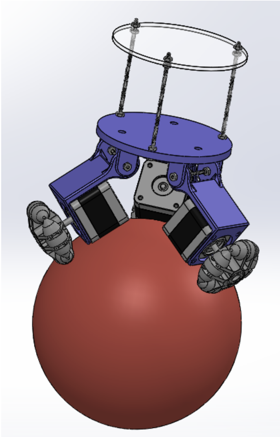
I designed my chassis with inspiration from similar projects using Solidwork CAD to create 4 part adjustable base. Each motor housing component is attached to the main chassis separately, so the angle can be adjusted, which allowed me to test on various sizes of balls.
Building the Structure and Fundamental Electronics
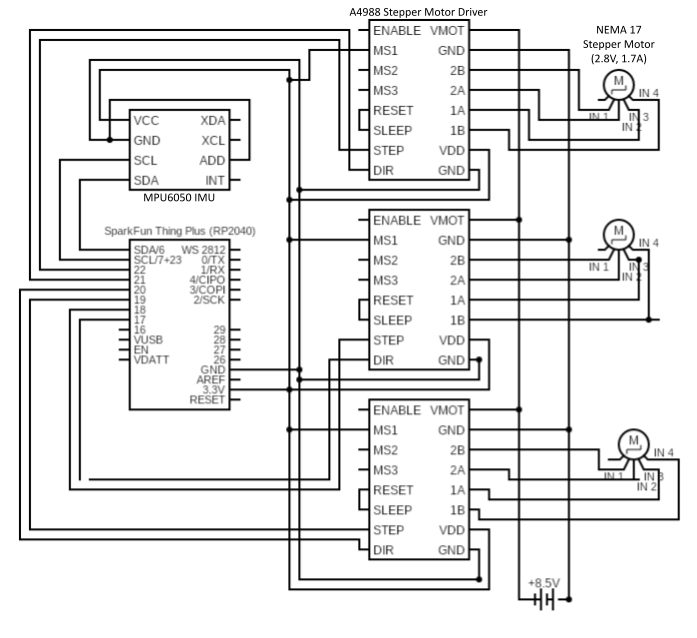
After printing and assembling the chassis pieces, I mounted the 3 motors with 3 motor drivers and a RP2040 ThingPlus microcontroller and started with the basic control of one motor, working on a script to step one wheel at a time.
Simultaneous Motor Control
The next step was to simultaneously step three motors. This proved to be a more difficult task than anticipated, as it seemed one motor would interfere with the other’s power source. However, after switching to drivers with a higher voltage rating, I was able to step each motor sequentially.
Once I could send alternating stepping commands to each motor, the base could perform basic directional movement including spinning in place and uniaxial paths (forwards, backwards, sideways).
Twist Commands
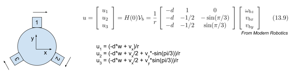 Deriving wheel rotation rate from a twist
To make a truly omnidirectional base, the next step was to follow any twist, which require stepping the motors at different frequencies. I started with the most basic form of a control algorithm, a polling loop that stepped each motor after a calculated number of sleep cycles resulting in a wheel RPM calculated by the omnidirectional base matrix equation.
Position Control
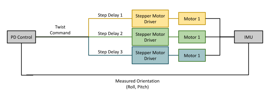
Once the mobile base was capable of following any twist command, it was time to integrate the IMU sensor and create a closed control loop. In my first iteration, only the accelerometer data from the IMU was used to calculate a roll and pitch, which were then used as inputs to the PD controller. The PD controller outputs an x and y velocity relative to the robot’s base frame, which are then converted to wheel speeds and finally step delays using the omnidirectional base equation shown above.
Self-Righting
The first milestone on the way to balancing was having the robot self-right itself back to a stable position on a ball. During testing, it became apparent that the motors would need to be stepped much faster in order for the robot to catch itself when the ball is not stabilized.
Design Adjustments
I redesigned the initial concept and chose to try a much larger ball in order to reduce the angle of lean and therefor the lever arm of the robot’s body over its center of mass. This, along with reducing to half steps, resulted in a smoother self-righting action but the wheel stepping was still prohibitively slow.
Control Adjustments and Sensor Tuning
I tried several different approaches to the control algorithm once it became apparent that a simple polling loop would not step the motors at the required frequency. When I realized system clock-based interrupts were not support on the rp2040, I attempted 3 separate timers, with each frequency updated after every update from the IMU. While this was successful in spinning the wheels much faster, three timers could not keep up with the step frequency and the reliability of the original polling loop was lost. This was most likely due to the constant resetting of the timers and the competing operations with no set priorities. Finally, I was able to merge the control strategies and create a single timer at a fixed frequency that then counted the number of cycles since the previous step and compared the count to the calculated step delay. This significantly increased the speed of the wheels without compromising a quick and accurate twist response.
The timer came with a trade off between the IMU measurement frequency and the maximum step frequency, but I found reading the IMU at approximately 10 Hz (a 100 ms delay between measurements) and polling the motors at 500 Hz (a 2 ms timer) was most successful in generating a fast enough reaction time while supporting a high motor stepping frequency.
With the wheels more reactive, noise in the IMU also became more apparent. I started with a rolling average filter, which worked well to smooth the signal and reduce spikes. The rolling average was effective at slower speeds, but with a much more reactive control loop, I wanted to explore more advanced methods of sensor fusion. A complementary filter allowed me to supplement the noisy accelerometer data with the steadier (but driftier) gyroscope data. This significantly reduced the steady state measurement spikes from up to +/- 40 degree spikes to negligible noise when the bot is stable.
Ultimately, after carefully tuning the PD gains and tweaking timer frequencies, my ballbot could balance for about 2 seconds before tipping over and losing control. I believe my biggest limitation was the tradeoff between measurement frequency and stepping frequency, and would like to try timer-based interrupts in future iteration or even separating the controller into multiple cores that could run the motor stepping commands and read the IMU simultaneously.
https://github.com/algarv/Ball_Balancing_Robot/